
Structural Engineering — Structural Analysis
The core analytical workflow for CivilTech: from defined actions to support reactions, shear, bending moment, and deflection—the quantities every member design depends on.
Introduction
Structural analysis uses equilibrium, compatibility, and material behaviour (linear or nonlinear) to predict how a structure responds to actions. For beams and frames, the usual outputs are reactions at supports, shear force V(x) and bending moment M(x) along members, and deflections for strength and serviceability checks.
In the handbook, this material sits in Section I: Chapter 1 (fundamentals—equilibrium, stress resultants), Chapter 2 (structural analysis—classical methods and idealisations), and Chapter 3 (dynamics—see the Structural Dynamics tool page). The calculators on this page focus on the static line: R, V, M, and δ.
For prismatic beams, shear and moment vary along the span; diagrams summarise V(x) and M(x) for design.
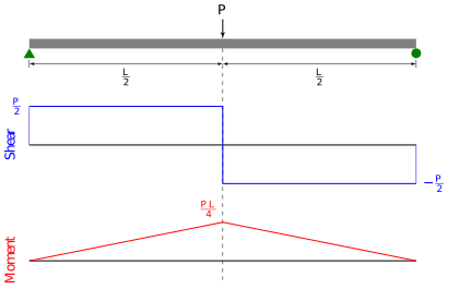

Core engine: reactions, shear, moment, deflection
This is the most important calculation path on the site: after load analysis, every structural check flows from R, V, M, and δ. Use the beam calculators below in order: reactions first, then internal shear and moment (same blocks quote Vmax, Mmax or critical values), then elastic deflection for serviceability. Calculators 1–4 and 6–7 cover reactions and resultants; Calculators 5 and 11 cover deflection (simply supported UDL and cantilever tip load).
- Beam reactions — Calculators 1–4, 6–7 (each block lists R).
- Shear force and bending moment — same calculators; SS UDL formulas above; other cases in their respective formula lines.
- Deflection — Calculator 5: δmax = 5wL⁴/(384EI) (SS UDL); Calculator 11: cantilever tip load.
What structural analysis yields
Typical outputs used in design and review:
- Support reactions (forces and moments) consistent with the structural model and load combinations.
- Internal resultants: shear V(x), bending moment M(x), axial force N(x), torque T(x) as required by the element type.
- Deformations and deflections for serviceability (slabs, cranes, façades) and for second-order or stability checks where relevant.
- Envelope diagrams or critical sections for proportioning members and connections.
Trusses and axial idealisation
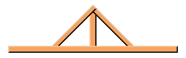
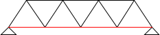
Pin-jointed truss idealisations carry loads primarily through axial forces in members (tension or compression). Joints are treated as pinned so that bar end moments are neglected; real trusses have some joint rigidity—check the validity of the model for your detail class.




Superposition (illustrative)
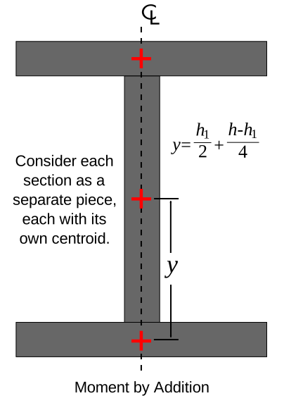
Linear elastic analysis allows complex load cases to be broken into simpler components; internal effects add where the principle applies. The sketch below illustrates combining moment effects for an I-beam idealisation—compare with your global analysis outputs.

When it is used
After loads are defined: frames, trusses, beams, slabs, and foundations are analysed to obtain design envelopes for ultimate and serviceability checks.
Real-world examples
- Office floor: beams supporting slab loads
- Portal frame: wind pushing on columns and rafters
- Truss bridge: bars carrying axial tension or compression
Calculator 1 — simply supported beam (UDL)
Uniform load along the span (e.g. floor loads spread onto the beam). Elastic formulas for a single span.
Simply supported — uniform load
End reactions, maximum shear, and maximum moment for a uniformly distributed load on a simply supported span.
Key terms
- Reaction
- Force or moment exerted by a support on the structure.
- Shear force (V)
- Internal force transverse to the member axis at a section.
- Bending moment (M)
- Internal couple resisting curvature; often maximum at mid-span for simple UDL beams.
Calculator 2 — cantilever beam (UDL)
One end fixed, the other free (e.g. a balcony slab edge). Maximum moment occurs at the fixed support.
Cantilever — uniform load
Fixed-end reaction and maximum moment at the support for a uniformly distributed load on a cantilever.
Key terms
- Cantilever
- Member fixed at one end only; the fixed end resists moment and shear from the whole span.
Calculator 3 — simply supported beam, point load at mid-span
Concentrated load P at mid-span (elastic, prismatic beam).
Point load at centre
Reactions, maximum shear, and mid-span moment for a concentrated load at mid-span on a simply supported beam.
Calculator 4 — point load at distance a from left support
Simply supported span L; concentrated load P at distance a from the left reaction (0 < a < L). Maximum moment occurs under the load.
Point load — general position
Left and right reactions and maximum moment under an off-centre point load on a simply supported span.
Calculator 5 — mid-span deflection (simply supported, UDL)
Elastic deflection at mid-span for uniform load (serviceability check). Uses flexural rigidity EI with E in GPa and I in mm4.
Mid-span deflection
Elastic mid-span deflection for a UDL on a simply supported beam from E, I, span, and load intensity.
Illustrative; verify units and load case against your model.
Calculator 6 — fixed-fixed beam (UDL)
Both ends fully fixed against rotation. End moments are hogging; mid-span moment is sagging (signs depend on convention).
Fixed ends — uniform load
Fixed-end hogging moment and mid-span sagging moment magnitudes for a uniformly loaded beam with both ends fully fixed.
Calculator 7 — cantilever, point load at free end
Concentrated load P at the tip; fixed end resists all bending.
Cantilever — tip point load
Fixed-end moment and constant shear for a concentrated load applied at the free end of a cantilever.
Calculator 8 — Euler buckling (elastic critical load)
Ideal pin-ended column analogy using effective length KL. Use for slender compression members when elastic buckling governs; compare with code column curves for real design.
Elastic buckling load
Euler elastic critical axial load Pcr for a pin-ended column analogy using effective length KL.
Illustrative elastic buckling; verify imperfection factors and design rules in the governing code.
Calculator 9 — axial stress (uniform member)
Average normal stress from axial force over gross area (illustrative; net section and block shear are separate checks).
Axial stress
Average normal stress σ = N/A from axial force and gross cross-sectional area.
Calculator 10 — symmetric two-bar truss (apex load)
Two equal inclined bars meet at the apex; vertical load P at the joint. Pin joints, only axial forces.
Bar force (compression if load downward)
Axial force in each bar of a symmetric two-bar truss under a vertical load at the apex.
Calculator 11 — cantilever tip deflection (point load)
Elastic deflection at the free end for a tip load (serviceability).
Tip deflection
Elastic deflection at the free end of a cantilever with a tip point load from P, L, E, and I.
Software and finite-element analysis
Continuous systems, 3D frames, plates, shells, nonlinear material or geometry, and code-specific member design usually require structural analysis software or FEA—not hand calculators alone. Examples (vendor sites; use current licences and training for production work):
- OpenSees — research-oriented nonlinear FE (open source).
- SAP2000 — general structural analysis and design.
- ETABS — building systems, lateral analysis.
- STAAD.Pro — general analysis and design workflows.
- Autodesk Robot Structural Analysis — analysis and BIM-linked workflows.
- RFEM — FEA for beams, surfaces, solids.
- Scia Engineer — integrated modelling and design.
Use hand formulas on this page for sanity checks and teaching; match boundary conditions and load cases to your model in software. No endorsement of a particular product—choose per project, code, and office practice.
Diagram sources
Educational schematics. Diagrams on this page were downloaded from Wikimedia Commons (Creative Commons or compatible licences) into Images/structural-analysis/—not reused from other topic folders. Verify licence on each Commons file page before reuse.