
Structural Engineering — Special Structures
Eight handbook chapters—specific structure types plus illustrative mechanics calculators (cables, bridges); full design still needs specialist software.
How this page relates to Section V (Chapters 22–29)
The handbook devotes one chapter per structure type—each with system behaviour, analysis idealisations, limit states, and often case-study-level discussion. This page cannot summarise eight chapters. Below, each heading is a topic map only; the cable and girder calculators are elementary mechanics for Ch. 25–26 intuition, not bridge or cable-stayed design.
Illustrations (bridges and grids)
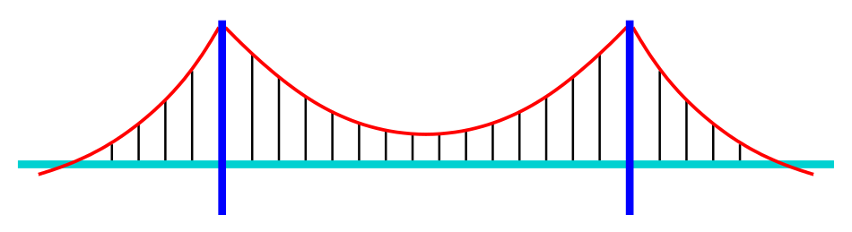
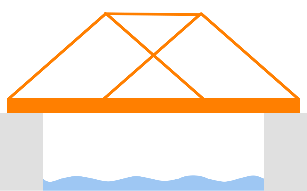
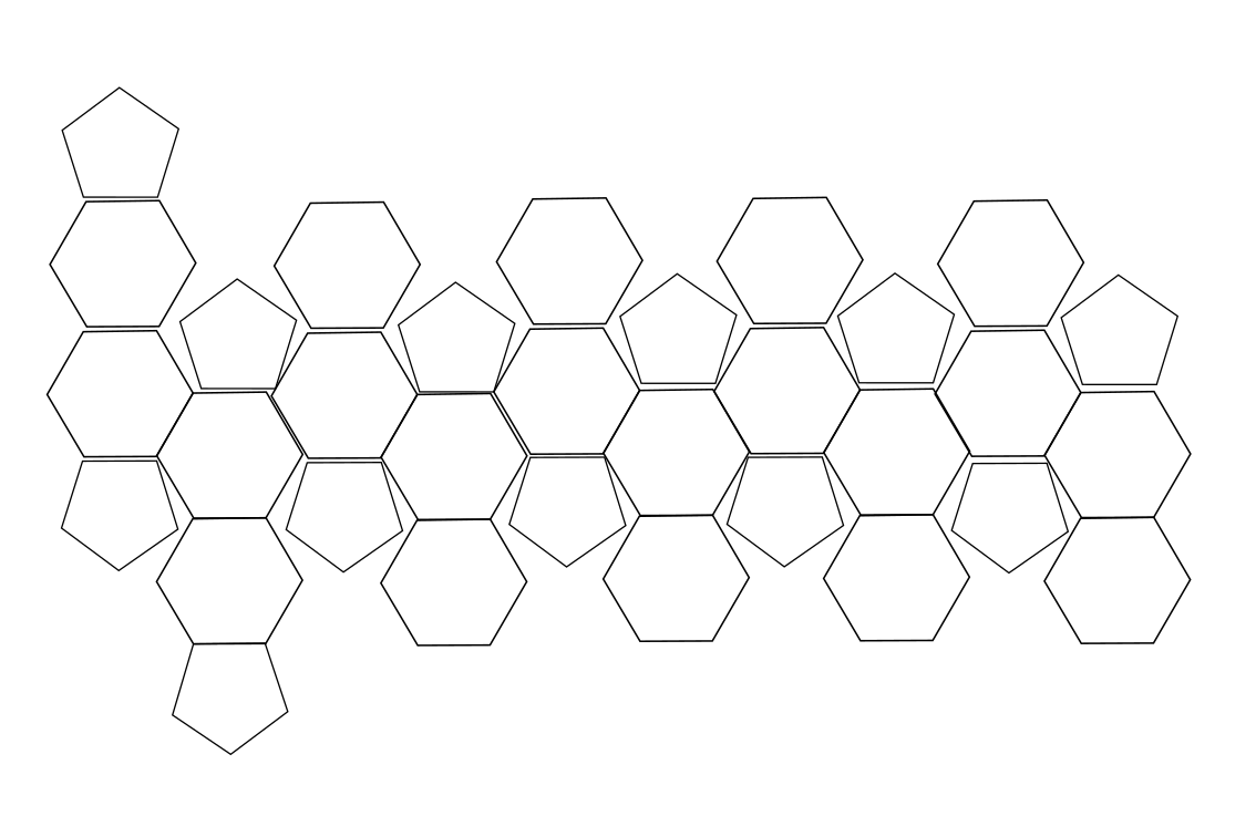
Section V spans long-span bridges, cable systems, and space grids. The diagrams are typology schematics from Commons—not project drawings.



What special structures design produces
- System-specific models — 3D frames, cable net or shell idealisations, staged construction and temperature effects.
- Limit states — Strength, stability (including lateral-torsional and shell buckling), fatigue, and often wind or seismic specialist studies.
- Execution — Fabrication tolerances, tensioning sequences, temporary works, and monitoring for long-span or sensitive structures.
Code and standards
Each structure type is governed by material codes (steel, concrete, aluminium, glass), bridge or building regulations, and often owner specifications for wind, fatigue, and fire. The handbook chapters orient the engineer; the signed standard and peer review set the bar on major projects.
Notation (on-page calculators)
- Cable sag — w load per unit length (N/m); L span (m); δ sag (m); H horizontal tension (N).
- Simple-span beam — P point load (kN); w UDL (kN/m); L span (m); M maximum moment (kN·m).
Advanced applications + teaching calculators
Section V systems need proper FE, wind tunnel, or geotechnical models for real projects. Below are simple formulas (cable sag, simple-span live load) to support Ch. 25–26 intuition—not code checks for major works.
Chapter 22 — Multistory frames (handbook scope)
Themes
- Gravity and lateral systems — Frames, cores, outriggers, belt trusses; vertical load path and redistribution.
- Drift and comfort — Serviceability limits, acceleration in wind; P–Δ and stability in tall frames.
- Modelling — 3D analysis, diaphragm rigidity, construction sequencing and creep/shrinkage in concrete systems.
Chapter 23 — Semirigid frames (handbook scope)
Themes
- Moment–rotation — Characterisation of joints (bolted end plates, flush angles, PR connections).
- Analysis — Linearised stiffness vs full nonlinear connection laws; drift and force distribution sensitivity.
- Design loop — Iterate connection capacity, stiffness, and member sizing.
Chapter 24 — Space frames (handbook scope)
Themes
- Topology — Single vs double layer; spherical and cylindrical grids; node types and fabrication tolerances.
- Behaviour — Predominantly axial forces; member buckling; support settlements and asymmetry.
- Loads — Snow, wind, maintenance; often large roof or canopy applications.
Chapter 25 — Bridges (handbook scope)
Themes
- Superstructure types — Beam, slab, box girder, arch, rigid frame; span ranges and construction method (precast, cast-in-place, launched).
- Moving loads — Influence lines, envelopes, dynamic allowance; load combinations per bridge code.
- Substructure — Piers, bearings, joints; temperature, creep, and settlement effects.
Chapter 26 — Cable bridges (handbook scope)
Themes
- Statics and geometry — Cable sag, stiffening girders, tower equilibrium; geometric nonlinearity.
- Dynamics — Aerodynamic flutter and vortex shedding on long spans; damping devices.
- Erection — Temporary states, tensioning sequences, monitoring.
Chapter 27 — Cooling towers (handbook scope)
Themes
- Shell action — Hyperbolic geometry; meridional and hoop forces under wind and dead load.
- Stability — Buckling of thin shells; reinforcement and stiffening rings.
- Environmental — Thermal gradients; corrosion in aggressive atmospheres.
Chapter 28 — Tunnels (handbook scope)
Themes
- Construction methods — Bored TBM, drill-and-blast, cut-and-cover, immersed tube.
- Ground interaction — Groundwater, face stability, settlement limits at surface.
- Lining design — Segment joints, thrust forces, seismic ovaling where applicable.
Chapter 29 — Glass structures (handbook scope)
Themes
- Material — Annealed vs tempered vs laminated; nickel sulphide risk in heat-treated glass.
- Support — Bolted point fixings, clamped edges, cable nets; redundancy and fallout protection.
- Human safety — Fragility, replacement strategy, blast or crowd loading where required.
Illustrative mechanics (Ch. 25–26)
Simple closed-form checks for cable horizontal tension and combined midspan loading on a girder—supplement to full bridge or cable-stayed analysis.
Calculator — cable horizontal tension (parabolic sag)
Chapter 26 — uniform load along span
Level span, uniform w
Horizontal cable tension H for a parabolic sag under uniform load along the span (H = wL²/(8δ)).
Calculator — simple-span beam (max moment)
Chapter 25 — moving load envelope (midspan point load)
Point + UDL
Maximum mid-span moment for a simple span with mid-span point load plus uniform load (M = PL/4 + wL²/8).
Software and special structures
Long-span bridges, cable nets, shells, and glass façades require advanced modelling—beyond the closed-form checks on this page. Examples (official vendor sites):
- OpenSees — nonlinear analysis including cables and shells.
- SAP2000 — general structural analysis.
- STAAD.Pro — analysis and design workflows.
- RFEM — FEA for shells, membranes, and cables.
- Scia Engineer — integrated modelling.
No endorsement—major bridges and unique structures typically need independent verification and domain specialists.
Diagram sources
Educational schematics. Files in Images/special-structures/ from Wikimedia Commons (separate downloads per §10.6).
- Bridge-suspension.svg — Tizio; suspension bridge typology.
- TrussBridge-diagram.svg — Themightyquill; truss elevation.
- Geodesic Polyhedron.svg — Pota12; geodesic pattern.