
Structural Engineering — Load Analysis
Establish design actions on a structure before analysis or member sizing. Loads are the input to every subsequent structural calculation.
Introduction
Load analysis is the systematic identification, quantification, and arrangement of actions (forces, pressures, and masses) that act on a structural system.
Before proportioning members or checking capacity, the engineer must define the actions the structure must resist. Design of beams, slabs, columns, connections, and foundations all depend on a consistent load model.
Actions are represented in the structural model as nodal loads, line loads, surface pressures, or equivalent static seismic effects. The same physical source (e.g. occupancy) may appear as different idealisations depending on whether you analyse a slab, a frame, or a foundation.

What load analysis produces
Typical outputs from a completed load-definition exercise, before member design or global analysis:
- Characteristic and design values for permanent (G), variable (Q), and environmental (wind, seismic, etc.) actions as required by the code.
- Distribution of floor and roof loads to beams and columns (tributary areas, pattern loading where applicable).
- Load combinations for ultimate limit state (ULS) and serviceability limit state (SLS) checks.
- Documentation of assumptions (use class, return period for wind, seismic risk class, soil–structure interaction simplifications) for the design basis.
Limit states and SANS 10160
South African practice uses SANS 10160 (and related parts) for the basis of structural design and actions on structures. Characteristic and design values are combined with partial factors for ultimate and serviceability limit states. The calculators on this page are illustrative; project-specific values, factors, and combinations must be taken from the current edition of the standard and the structural brief.
Notation (common symbols)
Symbols vary slightly by code; typical meanings in this context:
- G — permanent action (dead load); Gk characteristic permanent action.
- Q — variable action (imposed / live); Qk characteristic variable action.
- γ (gamma) — partial factor for actions; subscripts denote permanent or variable.
- q — surface load (kN/m²); w — line load on a beam (kN/m).
- W — often seismic weight or wind; check context in each clause.
Classification of actions
In limit-state design, actions are grouped so that characteristic values and partial factors can be applied consistently (see national standards such as SANS 10160).


Permanent actions (dead load)
Self-weight of structural and non-structural elements that remain in place (e.g. slabs, beams, cladding, fixed partitions).
Variable actions (live / imposed load)
Loads that change with occupancy or use: people, furniture, movable equipment, and stored materials.
Environmental actions
- Wind pressure on façades and roofs
- Seismic effects where applicable
- Snow or rain load where required by climate and code
Other actions
- Temperature-induced restraint and expansion
- Construction-stage loading and temporary bracing
Typical workflow
- Determine magnitude and direction of each relevant action
- Define position and distribution (concentrated, line, or area load)
- Combine actions according to ultimate and serviceability limit states
Why load analysis matters
Load definition is a prerequisite for structural safety and economy.
Safety
Underestimated actions can lead to inadequate resistance, excessive deflection, or instability. Overstrength is not automatic protection if the load model is wrong.
Economy
Overestimated actions produce heavier members and higher cost without proportional benefit. A balanced load model supports both compliance and efficiency.
Downstream use
Defined actions feed structural analysis (reactions, internal forces, deflections) and material design (reinforcement, buckling checks, connections).
When to perform load calculations
Project initiation
At the start of design: establish permanent and variable actions before member design or global analysis.
Change of use or geometry
Recalculate when occupancy category changes, floors are added, large equipment is installed, or lateral system or mass distribution changes.
Design verification
During checks against applicable codes (e.g. SANS) and for peer or independent review.
Alterations and refurbishment
When load paths change—removal of walls, new openings, extensions, or changes to cladding and roofs.
Design question
Structural adequacy is assessed against defined actions. The first question in design is not only “Is the member strong enough?” but “Which actions and combinations does the code require for this structure?”
Calculation tools and actions
The following sections cover common permanent and variable actions, environmental simplifications, distribution of floor loads to members, and combination rules. Each section includes a calculator for quick estimates; final design values must follow the governing standard (e.g. SANS 10160) and project-specific data.
Recommended order (input forces)
Work through the toolkit in sequence: (1) dead load → (2) live load → (3) wind → (4) seismic (if applicable) → (5) slab-to-beam UDL → (6) combinations. That matches the usual path from permanent/variable actions to environmental effects, then distribution and limit-state sums.
CivilTech groups these calculators by action type: permanent and variable actions first, then wind, then seismic overview. That mirrors how many engineers work through the load model; project design values still come from SANS 10160 and the brief.
1. Dead load (DL)
Permanent actions (structural fundamentals)
Permanent action. Weight of materials that remain fixed over the design life. For homogeneous prismatic members, weight is often derived from volume × material density. For floor slabs, an equivalent surface load (force per unit plan area) is frequently used.
Slab surface load: q = thickness × γ (kN/m²)
Typical applications: slab self-weight, masonry, steel section mass. Dead load is required for every permanent structure.
Dead load calculator
Slab surface load (kN/m²) or solid prism weight from thickness or L×W×H and material density.
Key terms
- Unit weight (γ)
- Weight of material per unit volume, usually expressed in kN/m³. It links geometry to gravitational load.
- Characteristic value
- A specified representative value of an action (often denoted Fk) used as the basis for design combinations in codes.
- Surface load (q)
- Force per unit area acting on a surface, typically kN/m², used for slabs and walls in plan.
2. Live load (imposed load)
Variable / imposed actions
Variable action. Loads from occupancy and use that can change in magnitude or position. Standards tabulate minimum characteristic imposed loads by use class; high-activity spaces (e.g. assembly or gym) often control design.
Use representative code values for the occupancy; the calculator below uses simplified indicative pressures for illustration only.
Live load calculator
Total indicative imposed load on the floor from occupancy-based pressure × plan area.
Values are indicative; confirm with SANS 10160 / client brief.
Key terms
- Imposed load
- Preferred term in many codes for variable loads from occupancy, furniture, and movable equipment (distinct from self-weight).
- Occupancy / use class
- Classification of building use that determines which tabulated imposed loads and reduction rules apply.
- Load reduction
- Codes sometimes allow reduced imposed loads on large floor areas or multiple storeys; check SANS 10160 for applicable rules.
3. Wind action
Wind engineering
Environmental action. Wind creates pressure and suction on exposed surfaces. Detailed design uses regional wind speed, terrain, height, shape factors, and dynamic effects. The tool below uses a simplified dynamic pressure from mean wind speed for illustration.
Resultant: F = q × A
Relevant for tall buildings, large façades, canopies, and slender elements. Always compare with code wind pressure and load cases for the project site.
Wind pressure & force calculator (simplified)
Dynamic pressure q = ½ρV² and resultant force F = q × A from wind speed and exposed area.
Key terms
- Dynamic pressure
- Pressure related to fluid flow kinetic energy; for wind, often derived from air density and velocity in simplified models.
- Pressure vs force
- Pressure (kN/m²) acts over an area; total wind force on a surface depends on pressure distribution and direction (drag, lift, suction).
4. Seismic action
Earthquake actions (fundamentals)
Inertial action. Ground acceleration imposes horizontal (and sometimes vertical) inertia forces proportional to mass. Codes express design seismic effects through spectra, response modification, or equivalent static base shear (e.g. coefficient × seismic weight).
Code formats: base shear V = Cs W (simplified notation)
Importance depends on seismic hazard; always use the applicable national standard and geotechnical/seismic input for the site.
Seismic force calculator (F = m × a)
Inertial seismic force from mass and horizontal acceleration (Newton’s law illustration).
Key terms
- Seismic weight (W)
- Mass of the structure (and often a fraction of live load) participating in seismic response, used in equivalent lateral force procedures.
- Seismic coefficient (Cs)
- Dimensionless factor relating design base shear to weight, derived from spectrum, period, and ductility assumptions in code.
5. Load distribution: slab to beam
Floor actions are often specified per unit area (kN/m²). Line-supported slabs transfer load to beams; a strip of slab of width equal to the tributary width contributes to the beam as a line load (kN/m).

Required whenever beams or girders are modelled as line elements supporting floor plates.
Slab → beam line load
Beam line load w = q × b from floor area load q and tributary width b.
Key terms
- Tributary width
- Width of floor (or roof) assumed to deliver load to a given supporting member, based on geometry of the slab panel.
- Uniformly distributed load (UDL)
- Load spread uniformly along a member, expressed in kN/m for beams or kN/m² for surfaces.
6. Load combinations
Structures are checked at ultimate limit state (ULS) and serviceability limit state (SLS). Actions are multiplied by partial factors (and combination factors where required) to form design combinations. The expressions below are common instructional forms; verify factors in SANS 10160.
Load combination calculator
Illustrative factored ULS combinations 1.2 DL + 1.6 LL and 1.35 DL from characteristic DL and LL.
Key terms
- Ultimate limit state (ULS)
- Design condition for strength, stability, and overturning, using factored actions and design material strengths.
- Serviceability limit state (SLS)
- Design condition for deflections, vibrations, and cracking, often using less severe load factors than ULS.
- Partial factor
- Multiplier applied to an action (or to resistance) to account for variability and consequence of failure, as defined in the code.
Software and load modelling
Defining actions, load cases, and combinations for real buildings and bridges is usually done in structural analysis, BIM, or specialist load tools—not spreadsheets alone. The calculators on this page are for illustration and sanity checks. Examples of platforms that support load definition, combinations, and analysis (official sites; use current licences and training for production work):
- OpenSees — research and advanced nonlinear analysis; load patterns defined in the model script.
- SAP2000 — load patterns, cases, and combinations for general structures.
- ETABS — building loads, lateral wind/seismic workflows, combinations.
- STAAD.Pro — load generation and combination with analysis.
- Autodesk Revit — BIM load schedules and coordination (often linked to analysis).
- Autodesk Robot Structural Analysis — loads and combinations with member design links.
- RFEM — surface loads, combinations, FE models.
- Scia Engineer — integrated loads and design.
No endorsement of any vendor—choose per project, code, and office standards. Always verify SANS 10160 (and related) factors and combination rules in the edition cited on your project.
Diagram sources
Educational schematics. Diagrams on this page are stored under Images/load-analysis/ and were obtained from Wikimedia Commons under Creative Commons licences. Authors: see file pages linked in each caption.
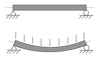
- Bending.svg — Daniel De Leon Martinez / Mircalla22
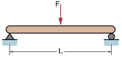
- Simple beam with center load — Hermanoere
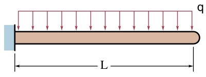
- Cantilever UDL — Hermanoere
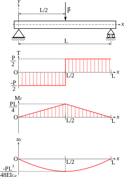
- Shear, moment, deflection diagrams — Christophe Dang Ngoc Chan