
Structural Engineering — Steel Design
Member design: beams (flexure), columns (axial), and connections (bolts, welds)—the steel stack that matches Handbook Ch. 4–6 and high-strength materials in Ch. 14.
Introduction
Steel design selects sections and connections so that design resistances exceed design demands from analysis. The handbook organises material as: Chapter 4 — steel structures (members and connections); Chapter 5 — frame design and advanced analysis; Chapter 6 — cold-formed steel; Chapter 14 — high-performance steel (higher fy, toughness, weldability). Typical limit states include yielding, buckling (global and local), and connection slip or fracture.
Hot-rolled sections, cold-formed members, and built-up girders each have different buckling and connection rules; SANS 10162 defines resistance factors and interaction for South African work.
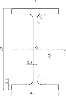
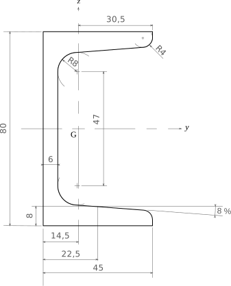
Rolled profiles are specified by designation (e.g. I-sections and channels in steel tables); properties such as area, Z, and S are listed per size for code checks.


What steel design produces
- Chosen member sizes (or confirmation of trial sections) with documented resistance at critical sections.
- Connection designs or design forces for connections (bolted, welded, pinned, moment-resisting).
- Compliance with serviceability limits (deflections, floor vibrations where applicable).
- Drawings and specifications referencing steel grade, bolts/weld types, and fabrication standard.
Code basis (South Africa)
SANS 10162 sets out limit-state design of steel structures (material partial factors, member resistances, connection rules). Actions and combinations come from SANS 10160. This site’s formulas are illustrative; always use the project’s code edition and national annexes.
Notation (common)
- fy — yield strength of steel (MPa).
- Z, S — plastic and elastic section moduli (mm³).
- φ (phi) — resistance (capacity) factor in LRFD-style expressions (value from code).
- γ — partial factor on actions or materials per limit-state format in the standard.
Examples in practice
- Beam: flexural capacity and lateral-torsional buckling between braces
- Column: axial compression with effective length and section class
- Connection: bolt group in shear/bearing or welded joint design
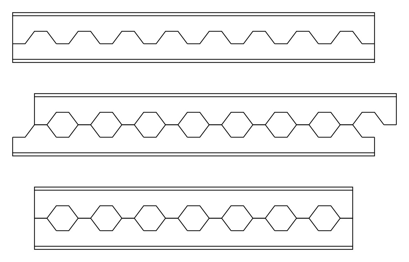
- Built-up or cellular beams: deeper profile with web openings (check shear, Vierendeel bending, and fabrication limits)

Handbook Chapters 4–6 and 14 — what they contain (not a summary)
The handbook devotes full chapters to rolled and built-up steel, frames, cold-formed steel, and high-performance grades. CivilTech does not replace that depth. Use this list only to know where topics live; member and connection design on site follows SANS 10162 and project specifications.
- Chapter 4 — Rolled and built-up members: flexure, shear, axial, buckling; bolted and welded connections; composite beams with concrete slabs.
- Chapter 5 — Frame behaviour: second-order analysis, P–Δ, braced vs unbraced frames, advanced analysis where plastic hinge or distributed plasticity models apply.
- Chapter 6 — Cold-formed steel: local, distortional, and lateral–torsional buckling of thin elements; different connection and bracing rules than hot-rolled work.
- Chapter 14 — High-performance steel: tougher, higher-strength grades; fabrication, welding, and fracture-related considerations (see also High-Performance Materials).
Handbook-linked calculators
Four quick checks aligned with the usual textbook layout (Ch. 4 member design + connections):
- Beam design (steel) — required plastic section modulus Zx,req from M and fy (major-axis flexure).
- Column capacity — gross-section axial yielding φ Ag fy (add buckling from the Stability page for slender members).
- Bolt design — illustrative shear resistance for a bolt group (bearing-type pattern).
- Weld design — illustrative longitudinal fillet weld strength.
Chapters 5–6 and 14 need software or code tables for frames, cold-formed sections, and HP grades—use the blocks below for core hand calculations only.
Calculator — beam design (required plastic section modulus)
Handbook — Chapter 4 (steel structures); flexural member sizing
LRFD-style illustration: required Zx from design moment M and yield strength fy. Compare rolled sections in steel tables to Zx ≥ Zx,req; then verify shear, lateral-torsional buckling, and deflection.
Section modulus check
Required plastic section modulus Zx,req from design moment, yield strength, and resistance factor (major-axis flexure illustration).
Key terms
- Plastic section modulus (Z)
- Geometric property used in plastic bending theory; differs from elastic section modulus S.
- Limit state design
- Factored loads compared to design resistance using partial factors per code.
Calculator — column capacity (gross axial yielding)
Handbook — Chapters 4–5 (members and frames); pair with effective length for buckling
LRFD-style tensile or compressive yielding of the gross section: Pn = Ag fy; design P = φ Pn. Compare with factored demand; for slender columns add buckling checks (see Stability page).
Gross section yielding
Design axial resistance from gross-section tensile or compressive yielding (φ Ag fy).
Calculator — bolt design (shear, illustrative)
Handbook — Chapter 4 (connections)
Nominal shear strength per bolt: Ab × Fnv with Fnv ≈ 0.6 fu (threads excluded in net area—this is a teaching check). Total: n φ Rn. Verify hole type, slip-critical vs bearing, and edge distances in SANS 10162 / project standard.
Bolt shear (bearing-type illustration)
Total nominal shear resistance for a bolt group from bolt area, ultimate strength, and resistance factor (illustrative).
Calculator — weld design (fillet, illustrative)
Handbook — Chapter 4 (connections); HP weld metal in Chapter 14
Design strength of a longitudinal fillet weld group: effective throat = 0.707 × leg size a; nominal stress on throat ≈ 0.6 FEXX (common LRFD pattern). Length L in mm. Use approved weld metal grades and QA for production.
Fillet weld design strength
Illustrative design strength of longitudinal fillet welds from leg size, total length, electrode strength, and φ.
Software and steel design
Full steel member checks, connection design, and detailing (including SANS / Eurocode / AISC workflows in practice) rely on specialist software and approved libraries. Examples of vendor ecosystems (official sites; licences and training required for production):
- Tekla Structures — modelling and steel fabrication information.
- Advance Steel — steel detailing and BIM.
- SAP2000 / ETABS — analysis with design modules.
- STAAD.Pro — analysis and steel design workflows.
- IDEA StatiCa — connection and detail resistance.
- Autodesk Robot Structural Analysis — member design integration.
- RFEM — steel/aluminum design add-ons.
No product endorsement—select tools to match your office’s code implementation and QA process. Hand checks on this page support understanding; they do not replace certified design output.
Diagram sources
Educational schematics. Files in Images/steel-design/ were downloaded from Wikimedia Commons into this repo (not copied from other topic folders). Confirm licence on each Commons file page before reuse.
- IPE_80.svg — IPE profile
- Upn_80.svg — UPN channel
- Castellated_beam.svg — cellular beam