
Hydraulics & Hydrology — Pipe Flow (Closed Conduits)
Pressure flow in full pipes: friction factor, head loss, and pump or gravity driving head.
Introduction
Closed-conduit flow fills the pipe cross-section; pressure can differ from atmospheric along the line. Steady, incompressible flow in long straight reaches is often analysed with the Darcy–Weisbach equation, using a friction factor f that depends on Reynolds number and relative roughness ε/D (Moody diagram or implicit Colebrook formula). Minor losses at fittings add to the line loss in reticulation and plant piping.
The calculator below uses a single supplied f; it does not iterate Colebrook or add minor losses automatically.
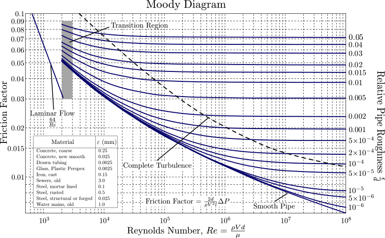


What pipe-flow analysis produces
- Head loss per reach and total from source to demand for a given flow.
- Pressure profile (hydraulic grade line) for strength checks and cavitation avoidance.
- Pump head and power requirements when static lift and losses are known.
- Inputs to transient (water hammer) studies when valves or pumps operate quickly.
Standards (South Africa)
Building and municipal water services: SANS 10252 (parts as cited in the project). Align pipe class, velocities, and surge protection with the client specification and national water-quality regulations. Industrial and fire systems may reference additional SANS or NFPA-aligned documents as required.
Notation (common)
- f — Darcy–Weisbach friction factor (same f as Moody chart).
- L, D — pipe length and internal diameter (m).
- V — mean velocity; g — gravity (9.81 m/s²).
- Re — VD/ν; ε/D — relative roughness.
- hf — head loss (m of fluid).
Examples in practice
- Water reticulation: looped networks with pumps and reservoirs (extended period simulation).
- Rising main: sum static lift, friction, and minor losses for pump selection.
- Cooling-water or process piping: head loss for control-valve sizing.
- Gravity sewer under pressure (siphons) or pumped discharge: verify available head.
Calculator — Darcy–Weisbach
Enter f, reach length L, diameter D, and mean velocity V; all must be positive. Uses g = 9.81 m/s².
Head loss
Darcy–Weisbach head loss hf = f (L/D) (V²/2g) for a full pipe reach (user-supplied f).
Key terms
- Friction factor (f)
- Darcy f from Reynolds number and ε/D (Moody / Colebrook–White).
- Minor losses
- Additional head loss at bends, valves, entries—often expressed as K·V²/2g.
Software and pipe network hydraulics
Distribution systems, fire networks, and industrial pipe runs use steady and extended-period solvers with pump curves and controls. Examples (official sites):
- EPANET — public-domain water distribution modelling (US EPA).
- OpenFlows WaterCAD — water distribution and fire-flow analysis (Bentley).
- AFT Fathom — incompressible pipe flow and system analysis.
- Autodesk Civil 3D — pipe networks and pressure pipes in civil projects.
- DHI MIKE — MIKE+ for water distribution and collection where applicable.
No product endorsement—verify boundary conditions, demand patterns, and pump curves against the project brief. This calculator does not model networks, transients, or fitting losses.
Diagram sources
Educational schematics. Files in Images/pipe-flow-closed-conduits/ were downloaded from Wikimedia Commons into this repo (not copied from other topic folders). Confirm licence on each Commons file page before reuse.