
Structural Engineering — Connections & Practical Design Details
Handbook Ch. 30, 32, 33—with on-page bolt, weld, bracing, and diaphragm calculators (illustrative).
How this page relates to Chapters 30, 32, and 33
Each chapter is a full treatment of connections, bracing systems, or floor/diaphragm behaviour. This page does not summarise those chapters. The sections below list major themes; the on-page calculators are small illustrations aligned with typical teaching examples in steel codes—not complete joint or diaphragm designs.
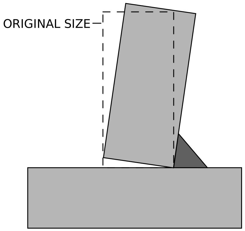
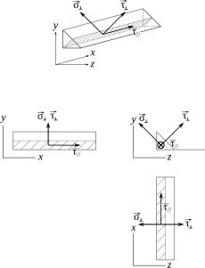
Illustrations (welds and joints)




What connections and detailing produce
- Connection design packs — Bolt schedules, weld symbols, plate thicknesses, and inspection classes matched to force transfer assumptions.
- Bracing continuity — Load path from diaphragm through braces to foundation; stiffness for drift and stability.
- Floor systems — Diaphragm stiffness, chord and collector design, and penetrations coordinated with MEP.
Code basis (South Africa)
Structural steel connections and members on South African projects follow SANS 10162 with project specifications for fabrication, welding procedures, and inspection. Concrete slabs and composite decks still tie to SANS 0100 for material and durability context.
Notation (on-page calculators)
- Bolt shear — n bolts; d diameter; fu ultimate strength; φ resistance factor.
- Fillet weld — a leg size; L length; FEXX electrode strength; φ resistance factor.
- Brace — V storey shear; θ angle from horizontal; F brace axial force.
- Diaphragm chord — M diaphragm moment; b width between chords; T chord tension.
Why this matters on site
Reviews and failures disproportionately involve joints, bracing continuity, and floor diaphragms. Member lines on a drawing are useless if the connection cannot develop the assumed forces, if bracing buckles or disconnects, or if the floor does not tie the lateral system together. Treat this topic as first-class, not an afterthought to beam formulas.
Chapter 30 — Welded connections (handbook scope)
Themes
- Weld types — Groove (CJP, PJP) vs fillet; throat, effective length, and load direction.
- Strength — Matching electrode to base metal; combined stress; block shear and prying in gusseted joints.
- Fabrication — Joint preparation, residual stress, lamellar tearing in thick T-joints; fatigue at cyclically loaded welds.
- QA — WPS, inspection levels, NDT access—execution per SANS 10162 and project ITPs.
The bolt and fillet calculators are the same teaching pattern as Steel Design—Chapter 30 adds groove welds, compound joints, and project-specific procedures.
Chapter 32 — Structural bracing (handbook scope)
Themes
- Bracing types — Concentric vs eccentric; chevron, X-brace, K-brace; buckling-restrained braces in seismic systems.
- Load path — From diaphragm to vertical bracing bents to foundation; accumulation of storey shear.
- Stability — Bracing member buckling; connection slip in bolted braces; stiffness for drift and P–Δ.
- Coordination — Architectural cores vs exposed bracing; retrofit and strengthening.
The brace force calculator (V/cos θ) is statics only—Chapter 32 covers system layout, capacity design, and code bracing requirements.
Chapter 33 — Floor systems (handbook scope)
Themes
- System types — Cast-in-place slabs, metal deck + concrete, precast planks with toppings, composite beams.
- Diaphragm action — In-plane shear and flexure; chord and collector forces; openings and re-entrant corners.
- Serviceability — Floor vibrations; stiffness for partitions and cladding.
- Integration — Penetrations, strengthening around holes, ties to lateral system.
The chord tension T = M/b model is a lever-arm idealisation—Chapter 33 and your diaphragm analysis define realistic force paths and capacities.
On-page calculators (Ch. 30, 32, 33)
Same bolt and fillet-weld models as Steel Design, plus bracing force from storey shear and chord force from diaphragm moment—teaching values only.
Calculator — bolt group shear (Ch. 30)
φ n Rn (illustrative)
Design shear resistance of a bolt group from n, d, fu, and φ (bearing-type illustration).
Calculator — fillet weld (Ch. 30)
Longitudinal fillet
Illustrative design strength of longitudinal fillet welds from leg size, length, FEXX, and φ.
Calculator — brace axial force (Ch. 32)
Storey shear V, brace angle θ from horizontal
Tension/compression demand
Brace axial force F = V/cos θ from storey shear V and brace angle θ from horizontal.
Calculator — diaphragm chord tension (Ch. 33)
M / b lever arm model
Chord force from diaphragm moment
Chord tension T = M/b from diaphragm in-plane moment M and width b between chord lines.
Software and connection modelling
Joint design, FE connection components, and BIM-linked fabrication often use specialist tools. Examples (official vendor sites):
- SAP2000 — general analysis; link member forces to connection design.
- STAAD.Pro — steel connection design modules (where licensed).
- Advance Steel — steel modelling and detailing.
- Tekla Structures — modelling and fabrication information.
No endorsement—verify connection assumptions against SANS 10162 and the project WPS/ITP.
Diagram sources
Educational schematics. Files in Images/connections-practical-design-details/ from Wikimedia Commons.
- Welding fillet distortion.svg — Wizard191.
- Brazing welding tee joint.svg — Gralo; tee reinforcement.
- Nomenclature contraintes dans une soudure.svg — Evariste le roi; weld stress notation.