
Structural Engineering — Other Material Design
Masonry, timber, and aluminium—each with distinct strength models, connections, durability, and code clauses (not steel or concrete).
Introduction
Brick, block, stone, engineered wood, and aluminium extrusions are common where architecture, weight, or corrosion resistance drives the choice. Behaviour under compression, shear, and bearing differs from steel and RC; connections and moisture or fire exposure often govern. Design must follow the appointed standard for each system.
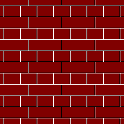
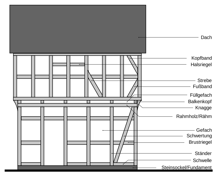
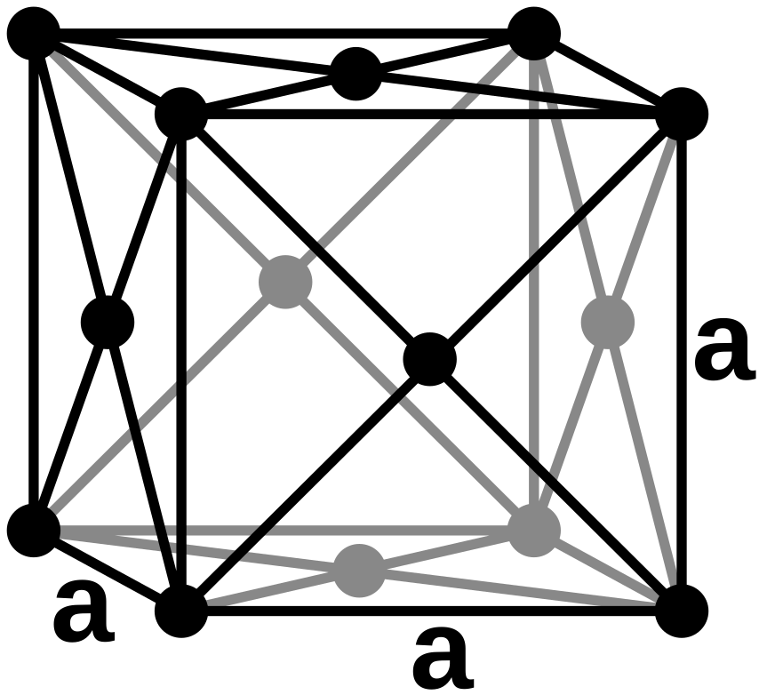
The diagrams below illustrate brick bond layout, timber framing elements, and the face-centred cubic (FCC) lattice—aluminium in the solid state is typically FCC, which underpins elastic properties used with member buckling checks.



What other material design produces
Typical outputs and decisions for these materials (beyond generic structural analysis):
- Masonry — Compressive and flexural resistance of piers and walls, bed-joint shear, ties to diaphragms, and detailing at openings and movement joints.
- Timber — Adjusted member capacities, connection design (splitting, withdrawal), creep and moisture effects, and fire protection where required.
- Aluminium — Deflection-sensitive sizing, local and overall buckling, weld-affected zones, alloy temper, and fatigue at cyclically loaded details.
Code basis (South Africa)
Actions and combinations follow SANS 10160 (or the edition specified on the project). Material resistance and execution follow the appointed SANS parts for masonry, timber, and aluminium—confirm the standard numbers and national annexes in your design brief; the calculators on this page are not a substitute for those clauses.
Notation (illustrative)
- Masonry — P axial load; An net area; f average compressive stress on An.
- Timber — Fb base bending reference; CD, CM, CF adjustment factors; F′ adjusted reference.
- Aluminium — E, I, A; KL effective length; σcr elastic Euler stress on gross area.
How this page relates to handbook Chapters 9–11
Each of Chapters 9, 10, and 11 in Handbook of Structural Engineering is a full treatment of its material—material properties, limit states, detailing, and code-style workflows. This page does not summarise those chapters. What follows is a topic map: the main design threads and failure modes engineers work through, so you can place the handbook (and your SANS standard) in context. The calculators further down are one illustrative check each, not a substitute for chapter- or code-level design.
Chapter 9 — Masonry structures (handbook scope)
What the chapter addresses
Masonry design spans unit masonry (brick, block, stone), mortar and grout behaviour, wall and pier geometry, and interaction with floors, roofs, and lateral systems. Chapter 9 develops strength and stability for in-plane and out-of-plane response, not a single “formula for walls.”
- Actions and resistance — Combined axial compression and bending (in-plane and out-of-plane), eccentricity, slenderness, and effective stiffness; bed-joint and collar-joint shear; bearing under concentrated loads.
- Stability and layout — Lateral support spacing, bracing, movement joints, ties to diaphragms, and behaviour around openings (lintels, pier strips, chases).
- Detailing and execution — Bond patterns, reinforcement and grouting where used, partial grouting effects, durability (moisture, freeze–thaw), and fire where the chapter or code ties masonry to protection requirements.
- What a real project adds — Seismic or wind-specific rules, soil–structure interaction at bearing, and verification of assumptions (support fixity, arching, composite action) from the structural model.
The masonry calculator on this page only computes average axial stress on a net area—useful intuition, not a capacity or interaction check from Chapter 9 or SANS.
Chapter 10 — Timber structures (handbook scope)
What the chapter addresses
Timber design covers sawn lumber, glued laminated timber, and other engineered wood products, with strength and stiffness varying by species, grade, moisture, load duration, and member size. Chapter 10 ties material properties to flexure, shear, bearing, connections, and stability, including ductility and brittle failure modes at joints.
- Reference design values — Published or characteristic strengths modulated by adjustment factors (load duration, wet service, temperature, size effect, etc.—exact factors follow your code; symbols on this page are teaching placeholders).
- Member checks — Bending, shear, deflection and vibration, compression (including column buckling and bearing perpendicular to grain), tension, and combined loading.
- Connections — Bolts, dowels, nails, plates, and splitting or withdrawal limits; capacity of net sections through fasteners.
- Serviceability and environmental — Creep under sustained load, moisture movement, and fire: protection ratings and char methods where the code requires them.
The timber calculator here multiplies a base stress by a few factors—an illustration of how adjustments chain together, not a full Chapter 10 or timber-code design line.
Chapter 11 — Aluminium structures (handbook scope)
What the chapter addresses
Aluminium structures use alloys and tempers with much lower elastic modulus than steel, so deflection and stability often govern before gross-section strength. Chapter 11 addresses proportioning of members and connections where local buckling, flexural–torsional buckling, and weld-affected zones are central.
- Section and material — Extruded shapes, classification of cross-section parts for local buckling, effective widths, and reduced strengths in heat-affected regions near welds.
- Stability — Flexural, lateral-torsional, and flexural–torsional buckling; comparison with code curves that go beyond elastic Euler stress for real sections and support conditions.
- Connections and durability — Bolting and welding practice for aluminium, galvanic compatibility, fatigue at cyclically loaded details, and corrosion protection where the environment demands it.
- Serviceability — Deflection limits and sometimes vibration-sensitive floors or façades.
The aluminium calculator uses Euler stress on gross area for an idealised strut—only a first-order elastic benchmark; Chapter 11 and your aluminium standard require full buckling and section checks.
Handbook-linked calculators (illustrative)
Teaching aids only—verify every value against the governing SANS material standard and project basis.
- Ch. 9 — average compressive stress on net area (axial check intuition).
- Ch. 10 — adjusted reference stress from load duration, moisture, and size factors.
- Ch. 11 — elastic Euler stress for an idealised strut (compare with code buckling curves).
Calculator — masonry axial stress (illustrative)
Chapter 9 — net section
Average stress
Average axial compressive stress f = P/An on the masonry net section.
Calculator — timber adjusted stress (illustrative)
Chapter 10 — adjustment factors
Reference design value F′b = Fb × CD × CM × CF (symbols as in NDS-style teaching; align factors with your code).
Adjusted bending reference
Reference bending design value F′ from base Fb and load duration, moisture, and size factors (illustrative).
Calculator — aluminium elastic buckling stress (illustrative)
Chapter 11 — stability
Euler stress on gross area
Elastic critical buckling stress σcr = Pcr/A from Euler Pcr for an idealised aluminium strut.
Software and design tools
Masonry panels, timber systems, and aluminium extrusions often need specialist member design, connection libraries, and 3D analysis—beyond the hand checks on this page. Examples (vendor sites; use current licences and training for production work):
- OpenSees — research-oriented nonlinear FE (open source).
- SAP2000 — general structural analysis and design.
- ETABS — building systems, lateral analysis.
- STAAD.Pro — analysis and design workflows.
- Autodesk Robot Structural Analysis — analysis and BIM-linked workflows.
- RFEM — FEA including shells and complex sections (useful for aluminium extrusions).
- Scia Engineer — integrated modelling and design.
No endorsement of a particular product—choose per project, code, and office practice. Align material models and connection assumptions with the governing SANS standard for each system.
Diagram sources
Educational schematics. Diagrams on this page were downloaded from Wikimedia Commons into Images/other-material-design/—not reused from other topic folders. Verify licence on each Commons file page before reuse.
- English bond.svg — brick bond pattern.
- Timber framing elements.svg — timber framing schematic.
- Face-centered cubic.svg — FCC lattice (crystallography).