
Structural Engineering — Stability & Buckling
Euler buckling load, slenderness ratio λ, and column stability (Pcr vs squash Py)—plus lateral-torsional and frame effects—aligned with handbook Ch. 31 and steel chapters.
Handbook Chapter 31 and related material — scope (not a summary)
Chapter 31 treats effective length and stability of columns and frames in depth (bracing, partial sway, story stability). Chapters 4–5 give steel member and frame design rules that use those concepts with code imperfections and column curves. This page’s Euler and slenderness tools are elastic teaching aids—production steel design uses SANS 10162 buckling and interaction checks, not Euler alone.
- Chapter 31 — K factors, braced vs unbraced frames, alignment charts, story buckling, member stability in structural systems.
- Chapters 4–5 — Column curves (inelastic buckling), beam LTB, bracing requirements, second-order analysis for sway.
- Related — Plate and shell buckling in other handbook chapters; concrete column slenderness in SANS 0100.
Introduction
Buckling is a failure mode where compressed members or plates deflect sideways or twist instead of failing in direct compression alone. The classical Euler solution gives the elastic critical load for an ideal pin-ended strut; Chapter 31 in the handbook develops effective length factors K for realistic end conditions. Real design adds imperfections, residual stresses, plasticity, and bracing—steel column rules in Chapters 4–5 complement these elastic idealisations.
Beams under major-axis bending can fail by lateral-torsional buckling if compression flange lateral support is insufficient. Frames may exhibit P–Δ instability under combined vertical and lateral loads—often checked with geometric stiffness in second-order analysis.
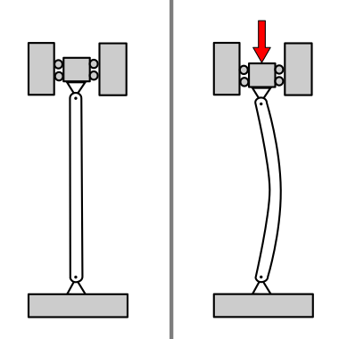

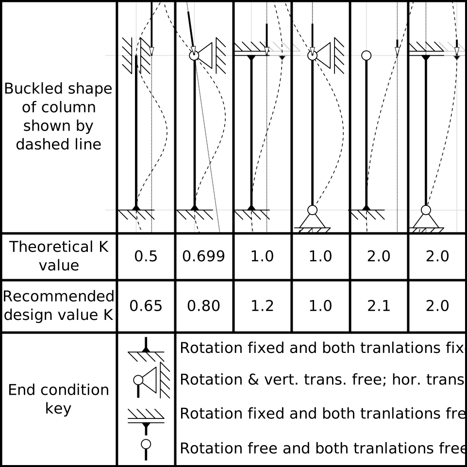

What stability analysis produces
- Critical loads or factors (elastic buckling, or design resistances per code) for members and bracing systems.
- Mode shapes (eigenmodes) showing likely buckle directions—used to verify bracing and torsional restraint.
- Second-order internal forces for sway-sensitive frames when required.
- Documentation of K factors, imperfection assumptions, and effective widths for plate buckling.
Code basis (South Africa)
Steel member stability (flexural, flexural-torsional, lateral-torsional) is governed by SANS 10162 together with actions from SANS 10160. Concrete columns and second-order effects are treated in SANS 0100. This page’s Euler formula is elastic and idealised; design resistance uses code curves, interaction, and limits on slenderness.
Notation (common)
- Pcr — elastic critical buckling load (N when E, I, L are consistent in N·mm).
- E, I — modulus and second moment of area about the buckling axis.
- L — member length between restraints; K — effective length factor.
- λ — slenderness (various definitions in codes); relates to elastic vs inelastic buckling.
Examples in practice
- Steel column in a braced frame: buckling about weak axis between floor levels.
- Roof beam: lateral-torsional buckling between purlin lines.
- Thin web or flange: local plate buckling before member buckling.
- Sway frame: global instability checked with second-order analysis or code amplification.
Handbook-linked calculators
- Euler buckling load Pcr = π²EI/(KL)² — ties to Chapter 31 via K.
- Slenderness ratio λ = KL/r with r = √(I/A).
- Column stability — compare elastic Pcr with squash load Py = Afy (conceptual link to steel column limit states in Chapters 4–5).
Calculator — Euler elastic buckling
Handbook — Chapter 31 (K); Ch. 1–2 (elastic stability concepts)
Ideal elastic column: E in MPa, I in mm⁴, L in mm, K dimensionless. Output Pcr in N and kN. Compare with factored axial demand and inelastic limits per SANS 10162 (steel) or the relevant code.
Critical load
Euler elastic buckling load Pcr from E, I, member length, and effective length factor K (consistent units).
Key terms
- Slenderness
- Ratio of member length to radius of gyration; higher slenderness increases buckling sensitivity.
- Effective length (KL)
- Equivalent pin-ended length representing end conditions.
Calculator — slenderness ratio
Handbook — Chapter 31 (effective length); member λ for buckling curves
Radius of gyration r = √(I/A); member slenderness λ = (K L) / r (consistent units—here L in mm, I in mm⁴, A in mm²). Compare with code limits for steel or concrete columns.
Slenderness
Radius of gyration r and member slenderness λ = (KL)/r from I, A, and effective length.
Calculator — column stability (elastic vs squash load)
Handbook — Chapters 4–5 (steel columns); Chapter 31 (K from above)
Compare the Euler elastic buckling load from the first calculator (same E, I, L, K) with the squash (yield) load Py = A fy for the gross section. If Pcr < Py, the idealised member is slender in the elastic sense; if Pcr > Py, yielding or inelastic buckling usually governs—use the project steel code, not Euler alone.
Squash load and Pcr/Py
Gross-section yield (squash) load Py and ratio to Euler Pcr using inputs from the Euler calculator (illustrative).
Software and buckling analysis
Linear buckling (eigenvalue) and second-order elastic/plastic analysis are used for real frames and shells. Examples (official sites):
- OpenSees — nonlinear analysis including geometric stiffness and buckling studies.
- SAP2000 / ETABS — buckling modes and P–Δ options.
- STAAD.Pro — linear buckling and steel design integration.
- Autodesk Robot Structural Analysis — buckling and steel code checks.
- RFEM — stability analysis per product modules.
- Ansys Mechanical — eigenvalue buckling and nonlinear collapse.
No product endorsement—match tools to your office’s QA and code implementation. Euler hand calculations educate; member and frame design must follow the project standard.
Diagram sources
Educational schematics. Files in Images/stability-buckling/ were downloaded from Wikimedia Commons into this repo (not copied from other topic folders). Confirm licence on each Commons file page before reuse.