
Geotechnical Engineering — Groundwater & Seepage
Flow of water through soil pores; controls pore pressures, effective stress, uplift, and piping risk.
Introduction
Groundwater movement in saturated soil is often described by Darcy's law: discharge velocity is proportional to hydraulic gradient. That yields seepage flow rates for dewatering estimates, uplift under slabs, and exit gradients at toes of dams or sheet piles—where piping and erosion must be checked.
Two- and three-dimensional problems use flow nets or numerical models; the calculator below is a 1D continuity check only.


Flow nets and 2D seepage
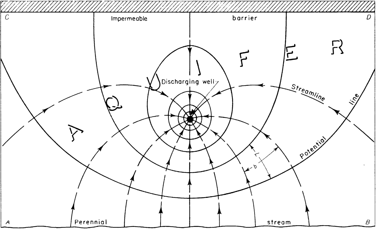
For plane strain conditions, equipotentials and flow lines form orthogonal families; the number of flow channels and head drops sets discharge and local gradients. Numerical codes extend this to layered soils, wells, and transient drawdown.

What seepage analysis produces
- Pore-pressure field or phreatic surface for effective-stress and uplift checks.
- Flow rate Q for dewatering pumps, cut-off performance, or leakage through dams.
- Exit gradient and path length for piping, filters, and drainage design.
- Input to slope stability and retaining-wall water loads when linked to the ground model.
Standards (South Africa)
Geotechnical design basis and groundwater-related limit states: SANS 10160-5. Permeability and laboratory/field tests: SANS 3001 (parts as specified). Align assumptions with the geotechnical investigation report, monitoring, and any dam, mine, or environmental permits.
Notation (common)
- k — coefficient of permeability (hydraulic conductivity), often m/s.
- i — hydraulic gradient (head drop per length along a streamline).
- v — Darcy (discharge) velocity; Q — volumetric flow rate.
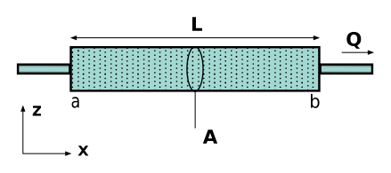
- A — gross cross-sectional area normal to flow (includes solids and voids).
- h — total head; u — pore pressure (linked through h = z + u/γw in simple setups).
Examples in practice
- Excavation beside a river: estimate inflow and pump capacity; check base uplift/heave.
- Embankment dam: seepage through core and foundation; filters and drainage blankets.
- Sheet-pile wall: flow under the toe and exit gradient on the excavation side.
- Well field: drawdown and interference between wells (superposition in linear aquifers).
Calculator — Darcy's law
Uniform flow normal to area A; gradient i and k positive. Output: Darcy velocity v and flow rate Q.
Seepage velocity and flow
Darcy velocity v = k i and flow rate Q = k i A through a gross cross-section area A.
Key terms
- Hydraulic gradient (i)
- Head loss per unit flow length along the path.
- Permeability (k)
- Soil property relating Darcy velocity to gradient (laminar flow regime).
Software and seepage analysis
Two- and three-dimensional seepage, transient drawdown, and coupled analyses use finite-element or finite-difference groundwater tools. Examples (official sites):
- GeoStudio — SEEP/W and related geotechnical groundwater modelling.
- PLAXIS — 2D/3D geotechnical analysis including flow.
- Itasca FLAC3D — coupled flow–mechanical modelling where required.
- USGS MODFLOW — regional groundwater flow (public-domain reference model).
- gINT — borehole and test data supporting parameter selection.
No product endorsement—calibrate models to site tests and monitoring. The calculator above is not a substitute for checked seepage analyses for dams, mines, or safety-critical excavations.
Diagram sources
Educational schematics. Files in Images/groundwater-seepage/ were downloaded from Wikimedia Commons into this repo (not copied from other topic folders). Confirm licence on each Commons file page before reuse.